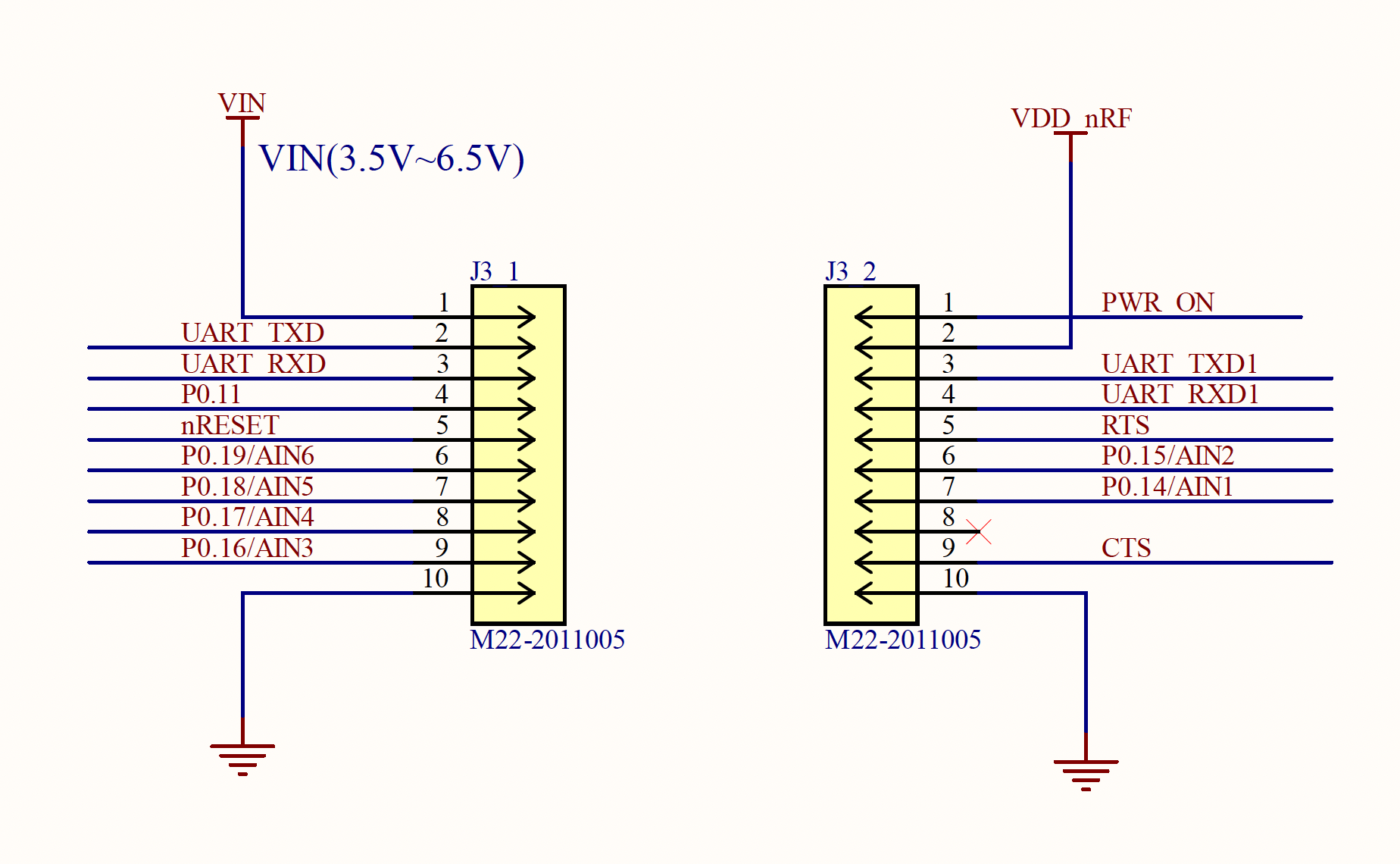
M1-N1 Pinout

Minimum connections
The following 4 connections are all that is needed to bring the M1-N1 alive. It can then operate and connect to the cellular network but will not have any connections to read sensors, ADC, or GPIO.
- VIN - J3_1 PIN1 - This must be connected to power.
- PWR_ON - J3_2 PIN1 - This must be connected to power.
- GND and GND J3_1 -PIN10 / J3_2 -PIN10
Optional Connections for Specific Application
To add functionality, it is necessary to use some pins to connect to sensors or as ADC inputs. The following pins can be connected for this purpose. The image above shows how our base software uses UARTs on various pins to connect with our sensor boards, but these are configurable in software for other functions.
Power / Reset
- VDD_nRF - J3_2 PIN2 - 3.3V regulated output. You can use this to power any sensor chips.
- nRESET - J3_1 PIN5 - Not needed unless you have an MCU or WDT chip to control and reset the processor.
General Connections
Use any of these for your various peripherals.
- AIN1/GPIO - J3_2 PIN7
- AIN2/GPIO - J3_2 PIN6
- AIN3/GPIO - J3_1 PIN9
- AIN4/GPIO - J3_1 PIN8
- AIN5/GPIO - J3_1 PIN7
- AIN6/GPIO - J3_1 PIN6
- GPIO - J3_1 PIN2
- GPIO - J3_1 PIN3
- GPIO - J3_1 PIN4
- GPIO - J3_2 PIN3
- GPIO - J3_2 PIN4
- GPIO - J3_2 PIN5
- GPIO - J3_2 PIN9
ADC Add-on Build
AIN1 through AIN6 are used for ADC support and any/all of these can be used in your hardware design. Signetik’s default ADC support is 4 channels using AIN3-AIN6
UART / SPI / I2C / GPIO
Any of the GPIO pins can be connected and used for these functions. They would be connected to hardware and then configured in software.
Comments
0 comments
Please sign in to leave a comment.